Compact body with numerous features.
UL/C-UL , CE Approved

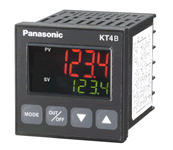
The KT4H uses our time-proven display system (negative type LCD + LED backlight) that is used in our timers and counters.
11-segment LCD makes letters easy to distinguish.
Largest PV indication in its class for easy readability even from a distance.
Also PV value can be switched among 3 colors so process status can be easily determined.
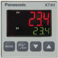
1.With negative type LCD and backlight, values can be read even under direct sunlight. Also, 11-segment LCD improves ability to distinguish alphanumerics.

2.Letter height of PV value has been enlarged to 12 mm/ .472 inch enabling it to be directly read even from a distance.
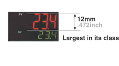
3.Ability of PV value to change into three different colors allows process status to be determined at a glance.

Capable of 4-point temperature selection by external input.
Control output can be turned ON and OFF externally.
3-phase heater burn-out detection function
Non-contact voltage output in heating/cooling control output available.
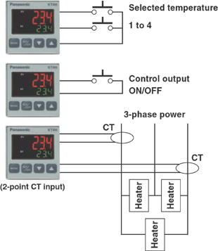
1.Four setting value (SV) selectable using external input. (option)
2.External ON and OFF switching of control output possible (option)
3.Heater burn-out alarm supports 3-phase heaters (option)
4.Supports voltage output for heating/cooling control (for SSR drive) (option)
1.Connect via Ethernet using our DLU (Web Datalogger Unit).
MEWTOCOL communications protocol is built in. Up to 31 units can be connected and data can be collected using a DLU or similar.

2.External tool port comes standard
Using the external tool port, all settings can be loaded and settings can be made.

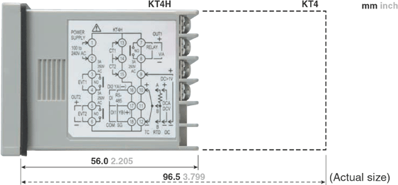
Control panel installation length has been shortened to the utmost.
The KT4H comes standard with ability to use any sensor (input): thermocouple (10 types), RTD (2 types), DC current (2 types), and DC voltage (4 types).
The operation mode uses “PID control” which allows a stable temperature to be maintained. Capable of high accuracy with an input span of ℃0.2% and a high-speed sampling period of 250 ms.
The switch layout has been changed and mode changes easier using the front keys.
Improved switch construction provides a much more positive clicking action.
Despite its compact size, protective structure conforms to IP66 (front panel only, when using rubber packing).
| Item | Specifications | |||||
|---|---|---|---|---|---|---|
| Size (W×H×D) | 48×48×62mm | |||||
| Rating | Supply voltage (Must be specified) | 100 to 240V AC | ||||
| 24V AC/DC | ||||||
| Frequency | 50/60Hz | |||||
| Power consumption | Approx. 8VA | |||||
| Rated graduation | Input type | Input range | ||||
| Thermocouple | K | -200 to 1370°C(-320 to 2500°F) | ||||
| -200.0 to 400.0°C(-320.0 to 750.0°F) | ||||||
| J | -200 to 1000°C(-320 to 1800°F) | |||||
| R | 0 to 1760°C(0 to 3200°F) | |||||
| S | 0 to 1760°C(0 to 3200°F) | |||||
| B | 0 to 1820°C(0 to 3300°F) | |||||
| E | -200 to 800°C(-320 to 1500°F) | |||||
| T | -200.0 to 400.0°C(-320.0 to 750.0°F) | |||||
| N | -200 to 1300°C(-320 to 2300°F) | |||||
| PL-II | 0 to 1390°C(0 to 2500°F) | |||||
| C(W/Re5-26) | 0 to 2315°C(0 to 4200°F) | |||||
| RTD | Pt100 | -200 to 850°C (-320 to 1500°F) | ||||
| -200.0 to 850.0°C(-320.0 to 1500.0°F) | ||||||
| JPt100 | -200 to 500°C(-320 to 900°F) | |||||
| -200.0 to 500.0°C(-320.0 to 900.0°F) | ||||||
| DC | Current | 4 to 20mA DC | -2000 to 10000 | |||
| 0 to 20mA DC | ||||||
| Voltage | 0 to 1V DC | |||||
| 0 to 10V DC | ||||||
| 1 to 5V DC | ||||||
| 0 to 5V DC | ||||||
| · Scaling and change to the decimal point position are possible for DC current and DC voltage input. · DC current input is supported with an externally mounted 50ohm shunt resistor (sold separately). | ||||||
| Multi-input | Thermocouple | K, J, R, S, B, E, T, N, PL-II, C (W/Re5-26) External resistor: Max. 100ohm (max. 40ohm external resistor for B input) | ||||
| RTD | Pt100, JPt100ohm 3-conductor system (Allowable input conductor resistance for each conductor: max. 10ohm) | |||||
| DC current | 0 to 20mA DC | Input impedance: 50ohm (Connect 50ohm shunt resistor between input terminals.) Allowable input current: max. 50 mA (when 50 ohm shunt resistor is used) | ||||
| 4 to 20mA DC | ||||||
| DC voltage | 0 to 1V DC | Input impedance: min. 1 M ohm, Allowable input voltage: max 5 V, Allowable signal source resistance: max. 2 kohm | ||||
| 0 to 5V DC | Input impedance: min. 100 k ohm, Allowable input voltage: max 15 V, Allowable signal source resistance: max. 100kohm | |||||
| 1 to 5V DC | ||||||
| 0 to 10V DC | ||||||
| Contact output | Relay contact (Contact material: Ag alloy) | (Must be specified) | 1a: 3A 250V AC (Resistive load), 1A 250V AC (Inductive load cosØ=0.4), Electric life: 100,000 times | |||
| Non-contact voltage | 12V DC±15%, Max. load current: 40mA (Short-circuit protected) | |||||
| DC current | 4 to 20mA DC Load resistance: Max. 550 ohm | |||||
| Alarm output 1 (EVT1) Relay contact (Contact material: Ag alloy) | Relay contact 1a: 3A 250VAC (Resistive load) Electric life: 100,000 times | |||||
| Alarm output 2 (EVT2) | The same as the one of Alarm output 1 | |||||
| Control mode | Actions mentioned below can be selected by key operation. [Default PID] PID (with auto-tuning function), PI, PD (with manual reset function), P (with manual reset function), ON/OFF action | |||||
| Target temperature setting | Primary setting/secondary setting/third setting/fourth setting (switched by external terminal) | |||||
| Accuracy | Thermocouple | Within ±0.2% of each input span ±1 digit or within ±2°C (4°F) whichever is greater However, R and S input; Within ±6°C (12°F) in the range of 0 to 200°C (0 to 400°F) B input 0 to 300°C (0 to 600°F): Accuracy is not guaranteed. K, J, T, E, and N input less than 0°C (32°F): Within ±0.4% of input span ±1 digit | ||||
| RTD | Within ±0.1% of each input span ±1 digit or ±1°C (2°F) whichever is greater | |||||
| DC current and DC voltage | Within ±0.2% of each input span ±1 digit | |||||
| Sampling period | 250ms | |||||
| Hysteresis (ON/OFF) | Thermocouple & RTD: 0.1 to 100.0°C (°F) DC current and DC voltage: 1 to 1000 (The decimal point place follows the selection) | |||||
| Proportional band | 0 to 1000°C(0 to 2000°F) The decimal point input: 0.0 to 1000°C(0.0 to 1000.0°F) DC current and DC voltage: 0.0 to 100.0% | |||||
| Integral time | 0 to 1000 seconds | |||||
| Derivative time | 0 to 300 seconds | |||||
| Proportional cycle | 1 to 120 seconds | |||||
| Allowable voltage fluctuation | When 100 to 240V AC; 85 to 264V AC When 24V AC/DC; 20 to 28V AC/DC | |||||
| Insulated resistance | 500V DC 10Mohm or greater | |||||
| Breakdown voltage | 1.5KV AC for 1 min between input terminal and power terminal, & between output terminal and power terminal | |||||
| Malfunction vibration | 10 to 55 Hz (1 cycle/min.), single amplitude: 0.35 mm 0.014 in (10 min. on 3 axes) | |||||
| Breakdown vibration | 10 to 55 Hz (1 cycle/min.), single amplitude: 0.75 mm 0.030 in (1 hour on 3 axes) | |||||
| Malfunction shock | X, Y & Z each direction for 5 times 98m/s2 | |||||
| Breakdown shock | Same as above, but 294m/s2 | |||||
| Ambient temperature | 0 to 50°C | |||||
| Ambient humidity | 35 to 85%RH (No condensation) | |||||
| Mass | Approx. 120g | |||||
| Waterproof | IP66 (applicable only to the front panel subject to rubber gasket employed) | |||||
| Display character height | PV: 12mm SV: 6mm | |||||
| Options | Heating/ Cooling control | Output (Must be specified) | Relay contact (Contact material: Ag alloy) | Control capacity 1a: 3A 250V AC (Resistive load), Electric life: 100,000 times | ||
| Non-contact voltage | 12V DC±15% Max. 40mA (Short-circuit protected) | |||||
| Heater burn-out alarm output Relay contact (Contact material: Ag alloy) | Specify either single-phase 20 A, single-phase 50 A, 3-phase 20 A, or 3-phase 50 A for rated heater current. Setting accuracy: within ±5% of rated heater current Relay contact 1a: 3A 250V AC (Resistive load), Electric life: 100,000 times | |||||
| Tool port | Communication interface C-MOS level Cannot be used at the same time as serial communication (option). *This port can only be used with the tool cable (AKT4H820). | |||||
| Accessories | Mounting frame | Comes with KT4H. | ||||
| Terminal cover | Sold separately. | |||||
| Communication type | Half-duplex |
|---|---|
| Communication speed | Select 2400, 4800, 9600, or 19200 bps using key operation. |
| Synchronization type | Asynchronous |
| Protocol | Modbus RTU, Modbus ASCII, MEWTOCOL (Slave) |
| Coding | Binary/ASCII |
| Interface | EIA RS485 compliant |
| No. of nodes | 31 |
| Maximum cable length | 1,000 m (cable resistance must be within 50ohm) |